
Biorobotics Laboratory BioRob
Adding an electric sense to a swimming snake robot
Project description
This project takes inspiration from the biological weakly electric fishes capacity to generate a near body electric field and to detects objects (for example predator or preys) entering this field. The final aim is to design a new sensing ability for the Amphibot II robot. With this sense we want to be able to detect wall obstacles and spherical objects and to evaluate their distance.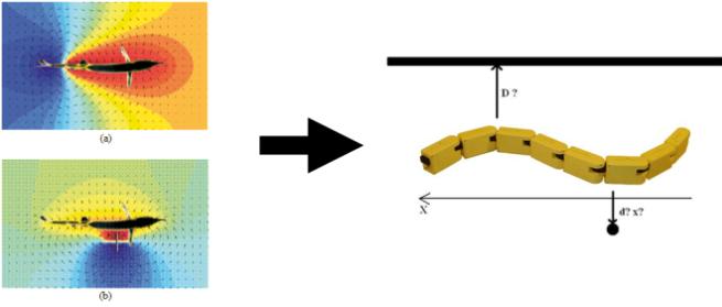
Figure 1. Left (a): The fish in an empty area, Left (b): The fish with an obstacle on the right. Source: Pascal Fua, Electric fish and EEG Tomography.
Right: The Amphibot swimming in an environment with virtual obstacles.
The first step was to design a modular device to experiment different hardware configurations we could later implement on the Amphibot. The functional part of this device contains electrodes to generate an electric field and to measure its perturbations. The shape and the material of this submersible part are the same than the one of the robot to be sure results keep consistent with the future application. Wires connected to the electrodes pass through a tube and can be connected to the electronic circuitry standing on the emerged part. Submersible parts are sealed to avoid contact between electronic and water. The floater size is calculated according to the global structure weight.
The electronic circuit consists of a square pulse generator of 5[V] and of two differential voltage measurer. These parts ensure filtering, amplification, offset add, differentiation and analogical to digital conversion of the measurated voltage. The connections between the 6 circuit entries and the 12 possible electrodes can be freely reconfigured. A central unit collects the values of each module trough a shared serial bus.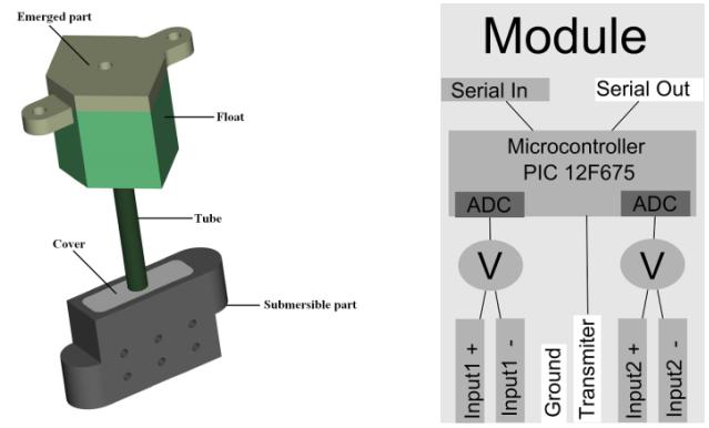
Figure 2. Left: 3D view of a module. Right: Schematic of the electronic circuit. V represent the analogical voltage differentiator and insure amplification, offset add and filtering.
After designing and building the modules, the electronic circuits and programming a communication protocol to transfer all measured values to a computer, the experiments could start. Several different configurations were tested on one module and compared in their effectiveness for wall detection. The best range was 4.5 [cm], what is equal to the corresponding inter electrode distance of the field generator. This is comparable with the fish performances. Later experiments on two modules shown that the range can be increased with larger inter electrode distance. Maximum range of 10 [cm] was obtained, giving good hopes to still increase the range with the full structure of 8 modules and doing efficient odometry or behavioral control on the real robot.
The detection of a resistive sphere was also experimented with one module and successful up to a distance of 4 [cm]. Some asymetric configurations of the electrodes allow to determine the distance of the object, as well as its position in the direction parralel to the module surface.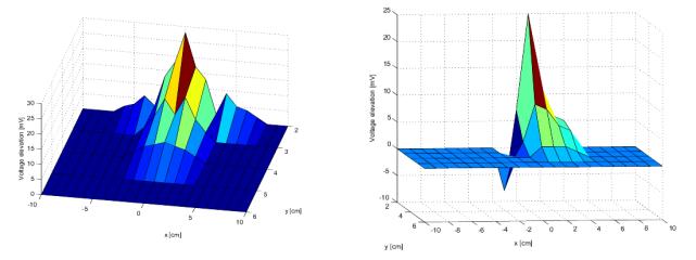
Figure 3. Object detection: Voltage shift on the receiver depending on a 4 [cm] resistive sphere position for two different configurations. Left: This configuration gives the highest range of detection. Right: The asymmetry of this configuration gives additional clues for detection.
Project report
You can download the project report here: rapport.pdf (PDF, 4.7 MB)
- Archived student projects
- Alain Dysli
- Alexandre Tuleu
- Anurag Tripathi
- Ariane Pasquier
- Aïsha Hitz
- Barthélémy von Haller
- Benjamin Fankhauser
- Benoit Rat
- Bertrand Mesot
- Biljana Petreska
- Brian Jimenez
- Christian Lathion
- Christophe Richon
- Cédric Favre
- Daisy Lachat
- Daniel Marbach
- Daniel Marbach
- Elia Palme
- Elmar Dittrich
- Etienne Dysli
- Fabrizio Patuzzo
- Fritz Menzer
- Giorgio Brambilla
- Ivan Kviatkevitch
- Jean-Christophe Fillion-Robin
- Jean-Philippe Egger
- Jennifer Meinen
- Jesse van den Kieboom
- Jocelyne Lotfi
- Julia Jesse
- Julien Gagnet
- Julien Nicolas
- Julien Ruffin
- Jérôme Braure
- Jérôme Guerra
- Jérôme Maye
- Jérôme Maye
- Kevin Drapel & Cyril Jaquier
- Kevin Drapel & Cyril Jaquier
- Loïc Matthey
- Ludovic Righetti
- Lukas Benda
- Lukas Hohl
- Lukas Hohl
- Marc-Antoine Nüssli
- Martin Biehl
- Martin Riess
- Martin Rumo
- Mathieu Salzmann
- Matteo Thomas de Giacomi
- Matteo Thomas de Giacomi
- Michael Gerber
- Michel Ganguin
- Michel Yerly
- Mikaël Mayer
- Muhamed Mehmedinovic
- Neha Priyadarshini Garg
- Nicolas Delieutraz
- Panteleimon Zotos
- Pascal Cominoli
- Pascal Cominoli
- Patrick Amstutz
- Pedro Lopez Estepa
- Pierre-Arnaud Guyot
- Rafael Arco Arredondo
- Raphaël Haberer-Proust
- Rico Möckel
- Sacha Contantinescu
- Sandra Wieser
- Sarah Marthe
- Simon Blanchoud
- Simon Capern
- Simon Lépine
- Simon Ruffieux
- Simon Rutishauser
- Stephan Singh
- Stéphane Mojon
- Stéphane Mojon
- Sébastian Gay
- Vlad Trifa
- Yvan Bourquin