Biorobotics Laboratory BioRob
Design of fish robot sensory system
In order to design and develop an autonomous fish robot, a sensory system must be used. This report presents the design of the sensory system of the fish robot.
Different types of sensors were studied, such as photo/light sensors (sensible to other parts of the spectrum as well as the visible part), humidity sensors, pressure sensors, inclinometers/accelerometers, electrosense, and others. These sensors will allow the "fish robot" to emulate, as closely as possible, the behavior of a live fish.
The inputs will be received through the sensors, then processed, and the resulting outputs will be specific movements of the robot which depend on the stimulus detected by the sensors. The input signal will be transformed into a digital signal which will be sent to the microcontroller, and depending on this input, an output signal will be generated. This will result in a certain movement of the robot.
The sensors tested
 |
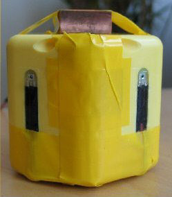
Photo sensors were mounted on a module to test whether or not these would enable the fish robot to follow a light source. Filters, that are not shown in the photgrapgh, were placed over the sensors to attenuate the light since the sensors' outputs were being saturated too easily. |
|
 |
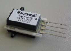
The pressure sensor shown below is used to detect the depth level of the fish robot. For testing purposes, it was mounted in a small plastic container which was sealed with silicone in order to keep water from reaching parts of the sensor that were supposed to stay dry. |
Results
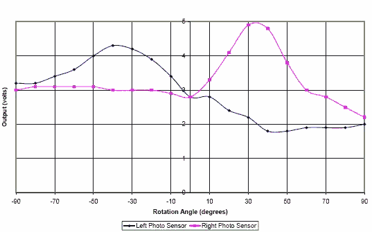
This graph shows the effects (photo sensor outputs) of rotating the module 90 degrees to each side on the neutral position. The neutral position being zero degrees, while facing the light source.

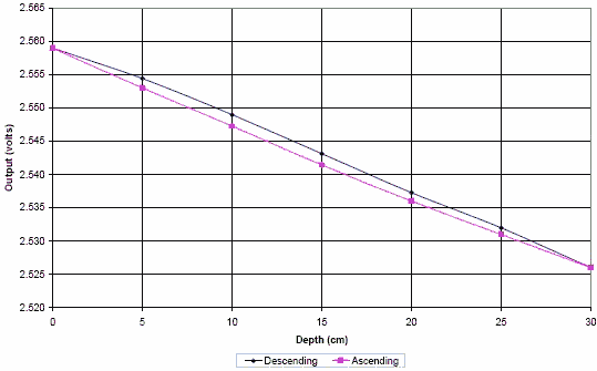
This graph depicts the slight hystereris that occured while descending and ascending the pressure sensor through water. This shows the average of seven trials, however, the pressure sensor showed excellent consitency in its output.

Documents
- Archived student projects
- Alain Dysli
- Alexandre Tuleu
- Anurag Tripathi
- Ariane Pasquier
- Aïsha Hitz
- Barthélémy von Haller
- Benjamin Fankhauser
- Benoit Rat
- Bertrand Mesot
- Biljana Petreska
- Brian Jimenez
- Christian Lathion
- Christophe Richon
- Cédric Favre
- Daisy Lachat
- Daniel Marbach
- Daniel Marbach
- Elia Palme
- Elmar Dittrich
- Etienne Dysli
- Fabrizio Patuzzo
- Fritz Menzer
- Giorgio Brambilla
- Ivan Kviatkevitch
- Jean-Christophe Fillion-Robin
- Jean-Philippe Egger
- Jennifer Meinen
- Jesse van den Kieboom
- Jocelyne Lotfi
- Julia Jesse
- Julien Gagnet
- Julien Nicolas
- Julien Ruffin
- Jérôme Braure
- Jérôme Guerra
- Jérôme Maye
- Jérôme Maye
- Kevin Drapel & Cyril Jaquier
- Kevin Drapel & Cyril Jaquier
- Loïc Matthey
- Ludovic Righetti
- Lukas Benda
- Lukas Hohl
- Lukas Hohl
- Marc-Antoine Nüssli
- Martin Biehl
- Martin Riess
- Martin Rumo
- Mathieu Salzmann
- Matteo Thomas de Giacomi
- Matteo Thomas de Giacomi
- Michael Gerber
- Michel Ganguin
- Michel Yerly
- Mikaël Mayer
- Muhamed Mehmedinovic
- Neha Priyadarshini Garg
- Nicolas Delieutraz
- Panteleimon Zotos
- Pascal Cominoli
- Pascal Cominoli
- Patrick Amstutz
- Pedro Lopez Estepa
- Pierre-Arnaud Guyot
- Rafael Arco Arredondo
- Raphaël Haberer-Proust
- Rico Möckel
- Sacha Contantinescu
- Sandra Wieser
- Sarah Marthe
- Simon Blanchoud
- Simon Capern
- Simon Lépine
- Simon Ruffieux
- Simon Rutishauser
- Stephan Singh
- Stéphane Mojon
- Stéphane Mojon
- Sébastian Gay
- Vlad Trifa
- Yvan Bourquin
